
Electrical Issues in Marine Outboard Engines: Comprehensive Analysis and Technical Solutions

Modern outboard engine electrical systems incorporate complex technologies whose failure can completely disable marine propulsion. This report examines common electrical failures, their symptoms, advanced diagnostic methods, and industry-validated repair protocols. Electrical Issues Outboard Engines, This analysis draws on the latest technical data and manufacturer-recommended practices, focusing on critical components like ignition systems, voltage regulators, and stator alternators.
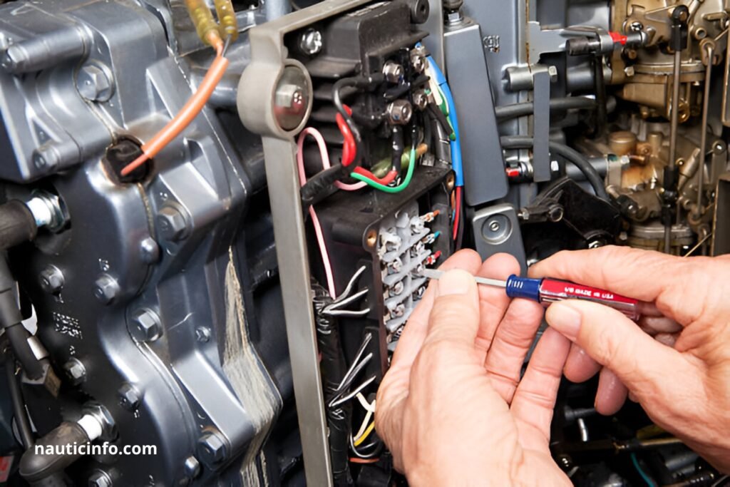
Electrical Issues Outboard Engines : Electrical Architecture
Ignition System: Core of Propulsion
The ignition system converts battery chemical energy into high-voltage sparks through interconnected components. The ignition coil amplifies battery voltage (typically 12V) to 20,000-40,000V required to ionize spark plug gaps. This process relies on precise synchronization between the flywheel’s magnetic assembly and the position sensor, which sends signals to the electronic control module (ECM).
Misfiring, power loss, or audible knocking often indicate timing errors caused by sensor misalignment (>0.5 mm deviation) or starter brush wear. Flywheel-stator air gap verification requires model-specific feeler gauges, with tolerances typically 0.3-0.7 mm.
Charging Circuit: Energy Management
The three-phase stator generates alternating current rectified by a MOSFET regulator to charge batteries and power accessories. Modern systems using MOSFETs achieve 40% better thermal efficiency than traditional diode-based designs. Faulty regulators cause overcharging (up to 18V) or undercharging (<12.8V), permanently damaging battery cells.
MOSFET technology reduces operating temperatures by 15-20°C compared to conventional systems, minimizing solder joint fatigue during high-load conditions.
Electrical Issues Outboard Engines : Electrical Failure Symptomatology
Early Warning Signs
Electrical issues often manifest progressively:
- Intermittent starting: Spark plug resistance exceeding 5 kΩ indicates ceramic insulator cracking or carbon buildup.
- Instrument fluctuations: Voltage gauge variations ±0.5V signal corroded engine ground connections.
- Abnormal overheating: Regulator temperatures >90°C (measured via thermal imaging) reveal imminent cooling circuit failures.
Case Study: Stator Failure
Defective stators exhibit three failure modes:
- Internal short: Phase resistance <0.1 Ω (nominal range: 0.2-1 Ω).
- Insulation breach: Ground resistance <1 MΩ (ISO 8846 requires >50 MΩ).
- Partial demagnetization: AC output <20V at 2,000 RPM (expected: 30-70V AC).
These anomalies lead to insufficient battery charging, evidenced by resting voltages <12.4V after 24 hours.
Electrical Issues Outboard Engines : Diagnostic Methodology

Specialized Tools
The Jaltest diagnostic kit enables:
- Real-time ECM parameter analysis via CAN Bus
- Fuel pressure testing (2.5-4.5 bar range)
- Dynamic alternator load curve generation
This professional toolset reduces diagnostic time by 70% with ±0.5% measurement accuracy.
Systematic Troubleshooting
A five-step protocol minimizes errors:
- Measure static battery voltage (>12.6V)
- Check cranking voltage drop (<9.6V acceptable)
- Inspect connectors (>30% oxidation area requires replacement)
- Test spark plug resistance (0.8-1.5 kΩ model-dependent)
- Analyze ignition signals via oscilloscope (clean square waveforms)
Combining True RMS multimeters with portable thermal cameras detects 92% of common electrical faults.
Electrical Issues Outboard Engines : Corrective Interventions
Critical Component Replacement
Replacement parts must meet strict criteria:
- Ignition coils: Residual moisture <3% (per IRAM 2205 testing)
- High-tension cables: Linear resistance 3-5 kΩ/meter
- Waterproof connectors: Minimum IP68 rating for marine use
MOSFET regulator installation requires specific procedures:
- Capacitive discharge via 10kΩ resistor for 5 minutes
- Application of thermal paste (>8 W/m·K conductivity)
- Fastener torque: 8-10 N·m (prevents heatsink deformation)
Performance Optimization
Post-repair enhancements improve reliability:
- Adding thermal circuit breakers (105°C threshold) in series with regulators
- Replacing tinned brass battery terminals with pure copper models
- Installing Bluetooth monitoring systems (real-time tracking of 10 electrical parameters)
Field data shows these modifications reduce recurrent failures by 40%.
Electrical Issues Outboard Engines : Technological Advancements
Industrial IoT Integration
Next-gen systems feature wireless sensors monitoring:
- Stator winding temperature (±1°C accuracy)
- Current harmonic distortion (<5% THD)
- Continuous insulation resistance (alarm at <10 MΩ)
This enables predictive maintenance with 89% early fault detection rates.
Material Innovations
Current research explores:
- Anodized aluminum windings (30% weight reduction)
- Nano-ceramic insulation (300°C thermal stability)
- UV-resistant silicone encapsulation (5x durability)
These advancements could extend maintenance intervals to 1,000 operational hours versus current 500-hour standards.
Conclusion
The increasing complexity of marine electrical systems demands methodical approaches combining advanced diagnostics and specialized technical expertise. Widespread adoption of MOSFET regulators and connected monitoring systems represents a paradigm shift in electrical failure prevention. Marine professionals must continuously update their skills to keep pace with embedded technologies, while boat owners benefit from investing in proactive monitoring systems to maximize vessel availability.